555 Timer Ic Schematic Diagram : Pin On Electronics / There is also a 556 dual version of 555 timer which consists of two complete 555 timers in 14 dip and a 558 quadruple timer which is consisting of four 555 timer in one ic and is available as a 16 pin dip in the market.
555 Timer Ic Schematic Diagram : Pin On Electronics / There is also a 556 dual version of 555 timer which consists of two complete 555 timers in 14 dip and a 558 quadruple timer which is consisting of four 555 timer in one ic and is available as a 16 pin dip in the market.. Daman shah june 5, 2021. In short, the 555 timer chip works by detecting threshold voltage levels. Because of their availability and ease of use, the 555 astable circuit is the common source of clock signal in many synchronous circuits. Being an integral part of electronics project, 555 timer ic is very often used in simple to complex electronics projects. This integrated circuit can be used in a variety of ways from which the basic one is to produce accurate and stable delays in electronic circuits.additionally, it is available in 8 pin dip and 14 pin dip.
With this information you will learn how how the 555 works and will have the experience to build some of the circuits below. The 555 timer ic is a very cheap, popular and useful precision timing device which can act as either a simple timer to generate single pulses or long time delays, or as a relaxation oscillator producing a string of stabilised waveforms of varying duty cycles from 50 to 100%. Because of their availability and ease of use, the 555 astable circuit is the common source of clock signal in many synchronous circuits. I hope you more understand. The block diagram of a 555 timer is shown in the above figure.
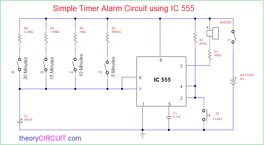
Pin On Electronic Circuit Diagrams from i.pinimg.com As we know 555 timer ic is one of the commonly used ic among students and hobbyists. Various light actuator and relay driver circuits are also further enclosed. Now, you can easily design the different timer circuits of 1minute,5 minute,10 minute and 15 minute using 555 timer ic with ease. Note this ckt diagram runs or burnt this type. Basic 555 monostable multivibrator circuit. 555 timer helpers schematic the addition of a capacitor to the trigger will not work for short output pulses as there The 555 timer is a simple integrated circuit that can be used to make many different electronic circuits. We have a large collection of simple and advanced projects using 555 timer ic.
Each mode of operation indicates a circuit diagram and its output.
Resistive network consists of three equal resistors and acts as a voltage divider. Although the schematic looks correct, this basic circuit may actually have a few negative aspects. In monostable mode, the duration for. Being an integral part of electronics project, 555 timer ic is very often used in simple to complex electronics projects. Because of their availability and ease of use, the 555 astable circuit is the common source of clock signal in many synchronous circuits. A collection of 555 circuits using the 555 timer as an astable oscillator with different duty cycles. 555 timer bistable example circuit. This is a basic circuit diagram of the 555 timer in the astable mode. Note this ckt diagram runs or burnt this type. The working modes of a 555 timer are astable, bistable, and monostable. Working modes of 555 timer ic. Pin 2 detects a voltage below 1/3 of the supply voltage to turn the ic on. Adjustable on off timer(using 555 astable mode) in this circuit a timer with cyclic on off operations is designed.
How much voltage and current will come. Connect pin 1 of a 555 timer ic to the ground. We need to set 555 timer in monostable mode to build timer. 555 datasheet 555 duty cycle 555 metronome 555 reset function 555 time delay relay inverted 555 timer pulse generator. If you are a beginner in electronics, you should learn the basics about a 555 timer ic, before you attempt to build 555 timer circuit or a full 555 timer project.
Schematic Circuit Diagram Of Internal Block Diagram Of 555 Timer Ic Proteus Simulation from circuit-diagramz.com Figure 2 shows the basic 555 timer monostable circuit. In short, the 555 timer chip works by detecting threshold voltage levels. Using the 555 timer ic in special or unusual circuits. We have seen in the last few tutorials that the 555 timer can be configured with externally connected components as multivibrators, oscillators and timers, with timing intervals ranging from a few microseconds to many hours. We can use this property of 555 timer to create various timer circuits like 1 minute timer circuit, 5 minute timer circuit, 10 minute timer circuit, 15 minute timer circuit, etc. Referring to the timing diagram in figure 3, a low voltage pulse applied to the trigger input (pin 2) causes the output voltage at pin 3 to go from low to high. This is a basic circuit diagram of the 555 timer in the astable mode. 555 timer circuits (133) browse through a total of 133 555 timer circuits and projects including the timer's datasheet.
555 timers are very popular in electronics.
How much voltage and current will come. Daman shah june 5, 2021. And, pin 6 detects a voltage above 2/3 of the supply voltage to turn the ic off. Pin diagram of 555 ic. Here you have separate on and off buttons to control an led. Now as shown in figure, there are eight pins for a 555 timer ic namely, 1.ground. Or separate the on and off switch for a machine. This circuit uses very basic components like 555 timer and 4017 counter. If you are a beginner in electronics, you should learn the basics about a 555 timer ic, before you attempt to build 555 timer circuit or a full 555 timer project. There is also a 556 dual version of 555 timer which consists of two complete 555 timers in 14 dip and a 558 quadruple timer which is consisting of four 555 timer in one ic and is available as a 16 pin dip in the market. We need to set 555 timer in monostable mode to build timer. One reduces the trigger sensitivity and the other will double the output pulse duration without increasing the r1 and c1 values. This is a basic circuit diagram of the 555 timer in the astable mode.
Collect all the required components and place the 555 timer ic on the breadboard. All we need to change the value of resistor r1 and/or capacitor c1. The 555 ic timer circuit above shows a very straightforward design where the ic 555 forms the central controlling part of the circuit. We need to set 555 timer in monostable mode to build timer. 555 datasheet 555 duty cycle 555 metronome 555 reset function 555 time delay relay inverted 555 timer pulse generator.
Simple Timer Alarm Circuit Using Ic 555 from theorycircuit.com The 555 ic timer circuit above shows a very straightforward design where the ic 555 forms the central controlling part of the circuit. All we need to change the value of resistor r1 and/or capacitor c1. This circuit uses very basic components like 555 timer and 4017 counter. In short, the 555 timer chip works by detecting threshold voltage levels. Pin diagram of 555 ic. The following example shows the 555 timer in bistable mode. The working modes of a 555 timer are astable, bistable, and monostable. With this information you will learn how how the 555 works and will have the experience to build some of the circuits below.
Sir do u have any igbt or mosfet 12v dc to 48v dc ckt diagrams.
The 555 is also very versatile, and can be used. Pin diagram of 555 ic. You can find the pin structure of a 555 timer ic in the circuit diagram shown above. We have seen in the last few tutorials that the 555 timer can be configured with externally connected components as multivibrators, oscillators and timers, with timing intervals ranging from a few microseconds to many hours. Monostable 555 timer circuits will automatically trigger and start a timing cycle when power is applied to the circuit. The timer's internal circuitry is largely responsible for this triggering but it is also caused stray or installed capacitance at the trigger input of the timer. We need to set 555 timer in monostable mode to build timer. 555 timer pin diagram and descriptions. And, pin 6 detects a voltage above 2/3 of the supply voltage to turn the ic off. Or separate the on and off switch for a machine. You can for example use it to reverse the direction of a robot when it bumps into a wall. The 555 timer ic is a very cheap, popular and useful precision timing device which can act as either a simple timer to generate single pulses or long time delays, or as a relaxation oscillator producing a string of stabilised waveforms of varying duty cycles from 50 to 100%. In short, the 555 timer chip works by detecting threshold voltage levels.
In this mode, the circuit of the ic 555 timer produces the continuous pulses with exact frequency primarily based on the value of the two resistors and 555 timer schematic. In this mode, the circuit of the ic 555 timer produces the continuous pulses with exact frequency primarily based on the value of the two resistors and.


0 Komentar